10+ vlan network diagram
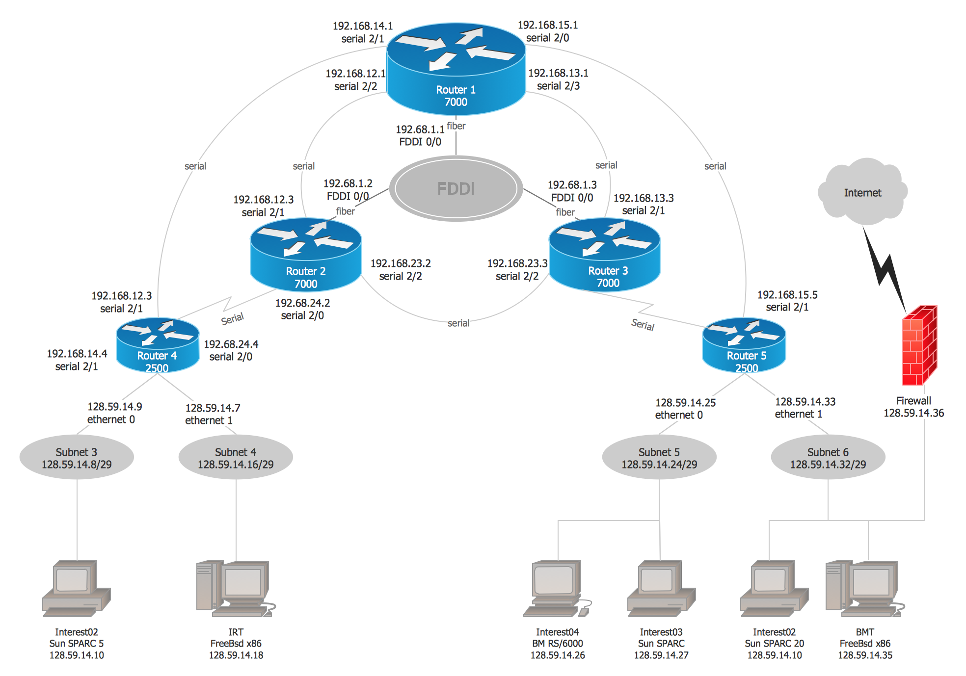
Click Edit under the topology diagram title. The diagram above shows two Catalyst switches connected to a FDDI backbone.

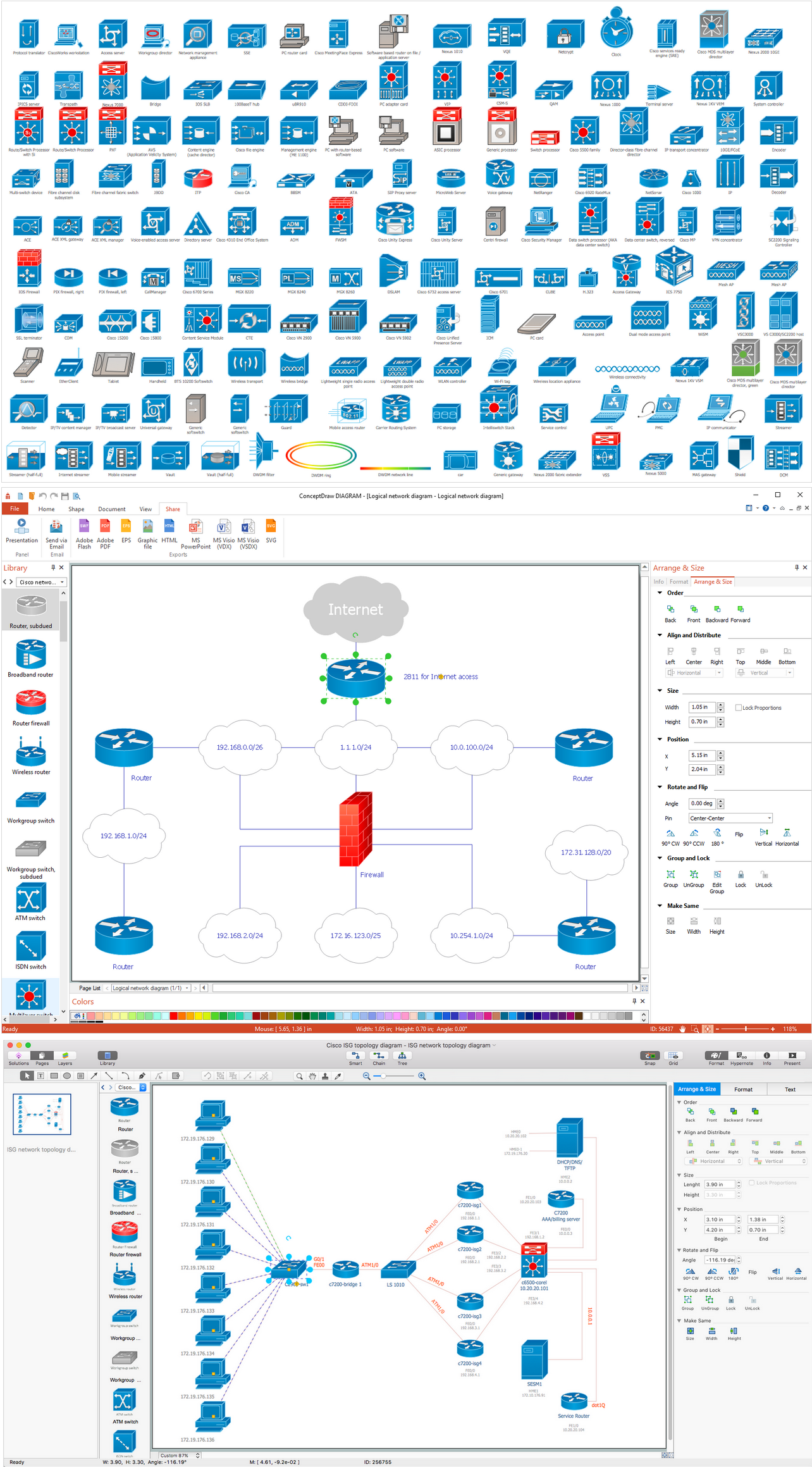
Cisco Isg Topology Diagram Cisco Networking Technology Cisco Networking Network Infrastructure
While one VLAN can be part of only 1 VRF on same device one VRF can have multiple VLAN assigned to it on same physical device.
. The first thing well do is enable HSRP. Physical Network Diagrams A physical network diagram as its name suggests shows the actual physical arrangement of the network components. Passive hubs dont amplify the electrical signal of incoming packets before broadcasting them out to the network.
Intelligent hubs add extra features to an active hub that are of particular importance to businessesAn intelligent hub is typically stackable meaning that its built in such a way that. In order to configure native VLAN switch port trunk native VLAN command is used. STP runs on bridges and switches that are 8021D-compliant.
Native VLAN does not carry a tag in the network so older devices easily understand when trunk links are sent. A schematic diagram of the 8021Q frame is shown below. Show spantree vlan_id Shows the current state of the spanning tree for this VLAN ID from the perspective of the switch.
Active hubs perform amplification much like a repeater. Native VLANs are recognized if they are not tagged to any trunks. This can cause incompatibility issues between devices that does not support such values.
This article applies to the following managed switches and their respective firmware. In the topology diagram of the switch click the name of the port group. The switches can be configured using dot IQ concept that is 8021Q tunneling frame.
Rootserver root esxcfg-vswitch -p VM Network 1 -v 10 vSwitch1. VRF starts from IP base license and IP service in catalyst switches. This diagram from the Cisco website shows them as well.
No license is required for VLAN creation. F01 - interface 2. To avoid compatibility issues it is recommended to use only these priorities.
The components of the Logical network shown in the above example are subnets like IP addresses masks and VLAN Id routers firewalls internet protocols routing domains traffic flow segments and voice gateways including many other network objects. VLAN works on layer 2 of OSI model. The F indicates that the NICport is most likely a Fast Ethernet type of connection.
Since VLANs are a Layer 2 technology the VLAN Tag is inserted within the Layer 2 header. These cookies enable the website to remember your preferred settings language preferences location and other customizable elements such. Use the standby command to configure HSRP.
A public virtual interface enables access to public services such as Amazon S3. Methods of launching VLAN hopping attacks. The difficulty is to decide which users should belong to which VLAN.
We will do this on the VLAN 1 interfaces of SW1 and SW2. By default the Catalyst 3550 switch acts as an L2 device with disablement of IP routing. It also provides management interface between kernelSo to transmit data using ndo_start_xmit youll need to create a socket assign an appropriate destination address and send the data via the socket.
1921681254 will be the virtual gateway IP address. The script following the diagram shows the commands you would use to configure the switch as shown in the diagram. Organize and Secure Your Network with a VLAN.
This means a logical network diagram will usually display subnets ie VLAN IDs addresses and masks routing protocols and network devices like firewalls and routers. In this diagram a small sample network with the Catalyst 3550 provides interVLAN routing between the various segments. This allows network paths to be segmented without using multiple device.
Create a virtual interface to enable access to AWS services. A VLAN hopping attack can occur in one of two ways. For example using the configuration above to add a VLAN ID of 10 to VM Network 1 which resides on vSwitch1 you must run the command.
He has implemented many. Ip address add address1000124 interfacebridge1 Specify which ports are allowed to access the CPU. These tunnels use the regular routing tables on the host to route the resulting GRE packet so there is no requirement that GRE endpoints are all on the same layer-2 network unlike VLAN encapsulation.
Line con 0 line vty 5 15. When intalling the appropriate switch modules and with the use of the 80210 SAID field a mapping between the Ethernet VLAN and 80210 network is created and as such all Ethernet VLANs are able to run over the FDDI network. The notation is denoting that there are multiple NIC interfaces on the router in the diagram and its making reference to this.
Functional cookies help us keep track of your past browsing choices so we can improve usability and customize your experience. SW1 SW2 configinterface Vlan 1 config-ifstandby 1 ip 1921681254. Port 102 handles traffic for both VLANs while port 101 is a member of VLAN 2 only and ports 103 and 104 are members of VLAN 3 only.
For more information see AWS Direct Connect connections. There are different flavors of STP but 8021D is the most popular and widely implemented. They help wireless driver to interface with rest of kernel and user space.
Configuring VLANs is actually very easy. F00 - interface 1. Two Major blocks of Linux wireless subsystem.
The 1 is the group number for HSRP. The gateway points to the VLAN 10 interface on the 3550. Interface ethernet switch vlan add portsether1switch1-cpu switchswitch1 vlan-id1.
When an Ethernet frame is exiting a Trunk port the switch will insert a VLAN Tag between the Source MAC address and. 0 4096 8192 12288 16384 20480. Use vlan-id that is used in default-vlan-id for switch-cpu and trunk ports by default it is set to 0 or 1.
The standard Layer 2 header in modern networks is the Ethernet header which has three fields. This document uses this network setup. Heres the referenced as Fa 0.
Destination MAC Address Source MAC Address and Type. In RouterOS it is possible to set any value for bridge priority between 0 and 65535 the IEEE 8021W standard states that the bridge priority must be in steps of 4096. Create a connection in an AWS Direct Connect location to establish a network connection from your premises to an AWS Region.
Ip default-gateway 101101 ip http server. This approach enables the sending of packets through any VLAN as the native untagged VLAN on the trunk and takes advantage of. Its always a good habit to differentiate hosts in a network either based on departmental differentiation.
Double tagging attacks occur when threat actors add and modify tags on the Ethernet frame. Logical Network Diagram Logical networks represent the flow of information in a particular network. In this case gre-1 is a tunnel from IP 101012821 which should match a local interface on this node to IP 101012816 on the remote side.

2 5 Years Later The Network Diagram R Homelab
Software Diagram Examples And Templates Network Diagram Examples Technical Flow Chart Example Diagram Examples
What Is The Use Of Vlans Quora

2 5 Years Later The Network Diagram R Homelab
2 5 Years Later The Network Diagram R Homelab

Interpreting A Network Diagram Computer Network Cisco Networking Computer Programming
Forwarding Data Between Vlans Networkacademy Io
What Is The Use Of Vlans Quora

Cisco Router Switch Real Shot Router Switch Router Cisco
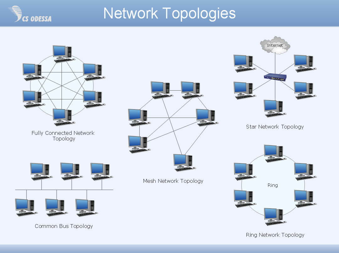
Network Topology Quickly Create Professional Network Topology Diagram Network Topology Drawing
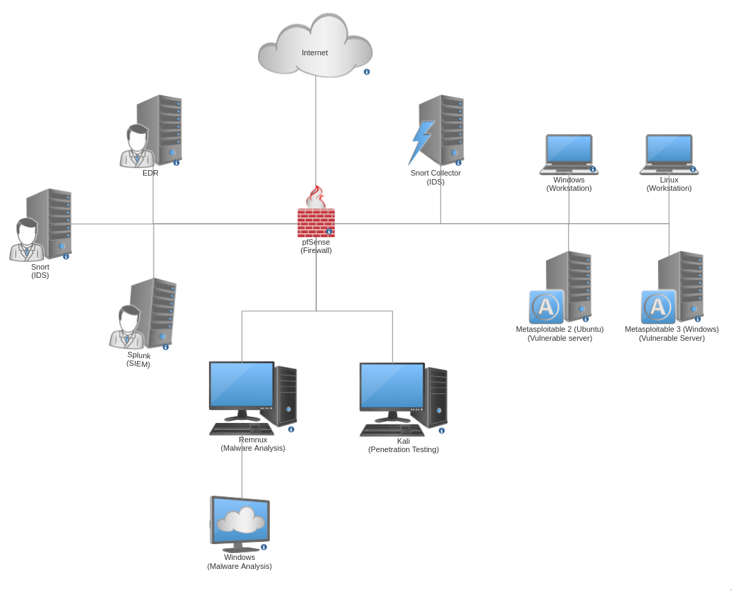
Building My Virtual Cybersecurity Home Lab

Computer Network Diagram Cloud Computing Technology Computer Network Cloud Computing Services

Network Diagram Guide Learn How To Draw Network Diagrams Like A Pro Networking Best Vpn Virtual Private Network

Software Diagram Examples And Templates Network Diagram Examples Technical Flow Chart Example Diagram Examples

Software Diagram Examples And Templates Network Diagram Examples Technical Flow Chart Example Diagram Examples
Network Topology Quickly Create Professional Network Topology Diagram Network Topology Drawing

Cisco Network Topology Diagram Cisco Networking Cisco Networking